
How many times have you heard it said that a central office air dryer is the heart of a cable pressurization system? It's a pretty simple analogy, but it is true. Like that tireless muscle that pumps blood through your arteries, the air dryer provides the life-force of the cable pressurization system. And when it's not healthy, the entire system is at risk.
In this AirTalk newsletter, we explain how air dryers can be properly set up and regulated to ensure adequate delivery pressure to the central office panels. We also discuss how dryers were installed and regulated in the past, why the original layout doesn't cut it today, and why "uphill" versus "downhill" pressure is so important.
First of all, it must be understood that there are two primary goals when regulating central office air dryers: 1) to maximize delivery pressure to the pipe alarm and distribution panels in the central office, and 2) to minimize the number of nuisance alarms (those meaningless flow increases and decreases) that result from fluctuations in air dryer output. The recommendations in this article directly address these important objectives.
Original Dryer to Panel Layout
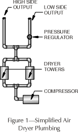
A typical central office air dryer consists of a number of basic components, including a compressor, two drying towers, and two outputs (both a high and low side). A pressure regulator, installed on the dryer's low side, controls output pressure on this side of the dryer. The high side output, which represents the "system pressure," is unregulated (Figure 1). In addition to these basic system components, two pressure gauges, mounted to the front of the dryer, provide a visual check of both system pressure and regulated low side output pressure. A flow rater indicates the total air flow produced by the dryer in Standard Cubic Feet per Day (SCFD).
The first central office air dryer installations were based upon the original Bell System Practices (BSPs). The BSPs specified that the high output side should be pneumatically plumbed to the office pipe alarm panels. Low side output was directed to the distribution panels (Figure 2). Because each pipe alarm panel contains a pressure regulator, the high side output (system pressure) from the air dryer could be individually regulated down at the panel from the maximum 20 to 23 Pounds per Square Inch (PSI) to the optimum delivery pressure of 10 PSI. Pressure regulators were not installed on the original B meter panels, so the low side output to these panels was regulated to 10 PSI at the air dryer.
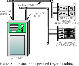
This original plumbing configuration provided marginal control for maintaining 10 PSI delivery pressure, especially to multiple distribution panels. With several distribution panels being fed from a single pressure feed via a central office manifold (Figure 2), there is no way to guarantee that the regulated 10 PSI will reach each of the panels. And, if dryer delivery pressure were to drop even slightly, none of the panels would receive the required 10 PSI.
Another problem with the original plumbing arrangement is that it caused variations in cable flow rates. While this may not have been important during the time of the first air dryer installations, accurate and reliable flow information is especially important today.
Alternating Air Dryers
Where this original design really suffers is when a second air dryer is required in the office as a backup to the primary dryer, or to provide an alternating source of delivery pressure to the system. In these situations the high side outputs from both dryers are sometimes plumbed together, as are the low side outputs (Figure 3). The problem with this technique is that even minor differences in the regulated low output pressure between the two dryers can cause fluctuating delivery pressures to the panels.
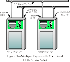
For example, as shown in Figure 3, one of the air dryers is putting out 10.2 PSI (on the low side); the other dryer holds a steady 10.0 PSI output. Depending upon how "tight" the alarming thresholds are set for the office, every time dryer output switches from Dryer A to Dryer B, the monitoring system will generate high flow alarms at the distribution panels. And, of course, these are not the type of alarms you want to receive in the middle of the night. They do not signal a serious or potentially system threatening condition (see "Dryer Shifting" below).
One of the ways to prevent these nuisance alarms from occurring is to regulate the low output of the dryer to 16 or 17 PSI and place a pressure regulator, set to 10 PSI, on the incoming feed to the panels. The higher output pressure at the dryer (uphill pressure) makes it possible for the secondary regulator (downhill pressure) to maintain a consistent 10 PSI. With this arrangement, you can be sure that each of the panels receives adequate delivery pressure. Any resulting high flow alarms at the distribution panels will more accurately signal a high flowing cable condition.
Dryer Plumbing Options
There are basically two options for improving the air dryer plumbing arrangements in offices with multiple air dryers. In both examples below, emphasis is placed on establishing an optimum 5 to 6 PSI difference between the uphill and downhill regulated pressures. (For suggestions about remote dryer nuisance alarms, see "Thoughts on Pole Mounted Compressors" below.)
Option #1:
This dryer-to-panel setup is slightly different than the BSP-specified method, in that only one output is used--in this case, the high side. An important benefit of using a single feed from the dryers to the pipe alarm and distribution panels is that there is less plumbing required. If you use the high side output, system pressure optimally should be between 20 and 23 PSI, and the low output sides must be capped (Figure 4).
A variation of this option is to take the individual high side outputs of the dryers and feed them into a manifold. Then a 1- to 2-inch inside diameter (ID) pipe/hose is used to feed the pipe alarm panels, and a minimum 1-inch ID hose is routed to the distribution panels. In either case, it is necessary to install a pressure regulator on the feed to the distribution panels--if you are using old-style panels. But if you are using distribution panels supplied by System Studies, you're in luck. Each of these panels is equipped with a high quality pressure regulator to ensure that delivery pressure can be set and maintained at 10 PSI.
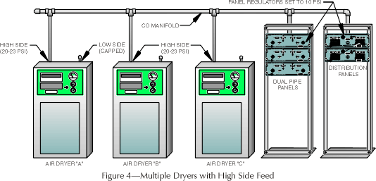
One of the problems with the plumbing arrangement described above is that not all air dryers provide the same system pressure. So, while you may expect each of the dryers to contribute an equal share of the total output, it's possible that only one of them may be doing the real work, especially if the dryer is a new one. For example, if Dryer A in Figure 4 were putting out 23 PSI, and the other two dryers output 19 and 20 PSI respectively, Dryer A would be doing all the work. Obviously, this defeats the purpose of using multiple dryers.
Option #2:
A second air dryer plumbing option is to use the low side of the dryers to feed the pipe and distribution panels and cap the high side output. This technique requires that you regulate low side output somewhere between 16 and 20 PSI (Figure 5). Once again, if you are using air dryers with reduced output pressure capabilities, this option will not work. But if your dryers can sustain 16 to 20 PSI, this option gives you the ability to regulate delivery pressure twice--once at the dryers themselves and again at or before the panels.
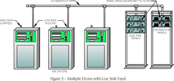
The important thing to remember is that the absolute minimum pressure required at the back of the panels is 15 PSI. If the pressure here is any less, the regulators at the panels are basically useless (see "Proving a Point" below). What you'll get is a lot of high flow alarms as well as fluctuating readings, and this is last thing you need if you have a system with 3,000 foot manifold spacing.
Since our pipe and distribution panels are equipped with pressure regulators, they are ideal for the type of applications described above. However, if you use distribution panels that are not equipped with a pressure regulator, you will need to install one on the incoming feed to the panels. Also, we recommend installing a 0-30 PSI pressure gauge somewhere before the pressure regulator to provide a visual indication of total delivery pressure to the panels (see "Dryer Monitoring" below).
Conclusion
Providing adequate delivery pressure to the cables in the field is just one the many functions of a healthy cable pressurization system. But it is also the most fundamental and important one.
Just as we need to keep our own blood pressure regulated to feel good and function at our best, the air pressure system requires the same type of attention. Keep the heart of the system in good shape, and you can minimize any cable complications that may arise.
Dryer Shifting
We've been asked on occasion if dryers should be set to alternate every 24 hours or only once a week. To be honest, we don't have any recommendations on this, other than suggesting that you check the manufacturing specifications for your particular dryer and follow their suggestion.
However, we do have some thoughts on what time of day your dryers should alternate. Basically, if you have dryers that are set up to shift every 24 hours, don't have them switch over at 2:00 or 3:00 a.m., for example. A better time to do this is at 9:00 or 10:00 a.m., or when you know someone will be around to take care of any possible problems that may occur. The important thing is to establish a plan that works best for your situation.
Thoughts on Pole Mounted Compressors
If you're getting a lot of high flow alarms at remote air dryers, there's a pretty simple explanation. The pressure in the dryer's holding tank can vary by as much as 20 PSI as tank volume is depleted and then replenished. If the maximum dryer output pressure is regulated to 10 PSI, for example, this pressure will drop slightly when tank pressure is low. Once the full volume of compressed air has been restored, regulated output again increases to 10 PSI, causing a high flow alarm in the process.
The best way to eliminate these types of nuisance alarms is to increase the regulated pressure output at the air dryer to 15 PSI or more. Then install an additional pressure regulator on the pneumatic feed to the cables, and set it at 10 PSI. This pressure differential will help to maintain a consistent 10 PSI to the cables.
Proving a Point
If you're wondering why we've placed so much importance on establishing and maintaining a good pressure differential between air dryer output and regulated pressure at the panels, here's why. Recently, we ran some tests that dramatically showed what happens to the regulated 10 PSI panel delivery pressure when the output from the air dryers drops just a few PSI.
First, we built a simple test fixture (see diagram below). We connected some tubing to an air compressor and placed both a pressure regulator and 0-30 PSI pressure gauge on the downhill side. Then we ran the tubing into one of our pipe alarm panels, which also contains a pressure regulator. At the end of the tubing (on the downhill side of the panel), we created a 90 SCFH leak. Panel delivery pressure was monitored with a C pressure gauge, and air consumption was checked on the panel's Flow Finder using a Flow Gauge.
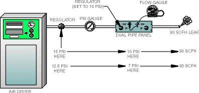
Here's what we found out. With the output from the compressor regulated to 15 PSI, we were able to easily maintain a solid 10 PSI at the panel. Then we began to regulate the compressor output down 0.5 PSI at a time. At around 12.5 to 13 PSI, the delivery pressure at the panel suddenly dropped from 10 to 7 PSI. The flow hadn't changed at all, but the inability to maintain an effective differential between compressor output pressure and regulated panel pressure essentially robbed 3 PSI from the system regardless of whether you're feeding 15 sheath miles of cable or 5 sheath miles.
If you'd like to view a video of this testing procedure, just give us a call. We put together a four minute explanation of the importance of good delivery pressure.
Dryer Monitoring
The number one cause of cable failure is air dryer breakdown. Existing dryer contact alarms provide information about high humidity, low water, etc., and they can signal a serious air dryer condition. But if you have multiple air dryers in an office and you're in charge of several offices, these alarms can sometimes be overwhelming--especially if they occur in the middle of the night. What you really need to know is when your system is in trouble, not when an individual dryer is acting up. You need to monitor the delivery pressure to the pipe alarm and distribution panels. That way if one of the dryers in an office fails, you'll be alerted if the other one can't carry the load.
Until recently, however, there wasn't a pressure transducer that could alarm high enough to be useful in this application. System Studies changed all that. We offer a 0-30 PSI High Resolution Pressure Transducer that can be installed in an office on the pressure feed between the dryers and the panels. This transducer will indicate if delivery pressure to your panels is low, and it will alarm only when you have a true emergency.
The 0-30 PSI Pressure Transducer can be designated in PressureMAP as a "$P" device, set to alarm at 14 PSI. So if one of your dryers shuts down, but the other is capable of supplying the minimum recommended 15 PSI to the back of the panels, you won't hear about the dryer problem until the morning. No sleep lost and no threat of damage to your system.
You can even customize the PressureMAP database to include all of your dryers (including contact alarms and individual office 0-30 PSI transducers) in one Transfer Office for easier monitoring and analysis. What could be easier?
© 1996-2018 System Studies Inc. All rights reserved.
(800) 247-8255 | (831) 475-5777