
Issue No. 46–March, 1994
Editor's Note: The following Gazette article contains excerpts from a System Studies primer covering the basics of cable pressurization maintenance. If you would like to read the complete primer, use this link.
Due to the major changes taking place in telephone operating companies, we have found that there are many people at various levels of the telco organization who do not have a firm understanding of cable pressurization. We thought it would be a good idea to go over the basics of air pressure for those of you who may not have had training in this area of outside plant maintenance. This information briefly addresses some of the key questions concerning air pressure.
Why are Telephone Cables Pressurized?
The biggest threat to telephone wires (conductor pairs) is moisture. For this reason, air is pumped into cables to keep the moisture out. Unfortunately, the integrity of the protective cable sheath (which is made of lead or polyethylene) is compromised when cracks develop. The cracks in the sheath or associated splice cases allow water to enter and electrolysis to occur, which results in faulted pairs within the cable.
The basic premise of cable pressurization is to keep the pressure within the cable in excess of the pressure that could be applied by standing water. To help achieve this objective, telephone companies establish minimum air pressure standards for cables in different environments.
What is Pneumatic Resistance?
Pneumatic resistance is the amount of resistance that air flow meets as it moves along inside the cable sheath among the conductors. What determines the amount of pneumatic resistance in a particular section of cable are its length, the gauge of the conductors, the type of insulation (PIC or pulp), and the number of pairs in the cable.
Pneumatic resistance must be taken into account when using pressure and flow measurements during leak locating along a route. Together, these three components comprise the important information needed to perform many of the successful leak locating formulas being used today.
How is Air Pressure Distributed?
The pressure comes from a mechanical air compressor and dryer, located somewhere near the telephone company cable vault. The equipment compresses or squeezes air molecules together within a given area to create greater air pressure. The amount of compression is measured in Pounds per Square Inch or PSI. The compressor supplies the air at approximately 10 Pounds per Square Inch (PSI), while the dryer removes the residual moisture. Essentially, this means that air with very low humidity is forced into the cables.
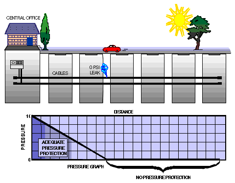
Depending upon the cable's age and a number of other variables, there will typically be leaks at various points along the cable run. The cable runs are usually thousands of feet long and, like a hose, the pressure in the cable diminishes as the length increases.
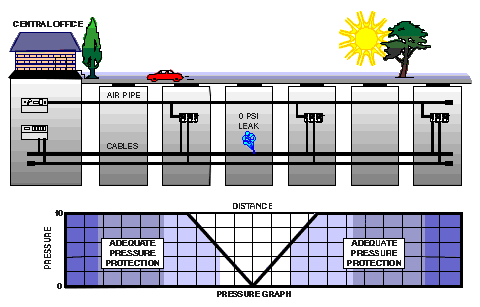
Due to the length of the cable routes and the inevitable leaks along it, the pressure must be re-established in the system at various points or the cable will be unprotected at substantial distances from the central office. One popular way of raising air pressure in the system is by using air pipe that follows the cable route and introduces pressure at various fixed points. Air pipe manifolds are connected to the air pipe to distribute air to the cables in the designated utility holes.
Should Maintenance Be Performed on a Routine Basis?
It is commonly thought that, once a cable leak has been found and fixed, the cable will be safe from moisture. After a repair, there is a natural tendency to conclude that "everything is okay" and that maintenance can be ignored until more leaks are found in the cable. This couldn't be further from the truth.
Nowadays, routine maintenance is often referred to as proactive maintenance. Many telephone companies are shifting towards a proactive approach to the outside plant in order to prevent subscriber calls, Public Utilities Commission (PUC) complaints, and even catastrophic failure. It's preventive medicine for the outside plant.
What is the Best Design for Protecting Cables?
The best engineering design for protecting cables is a dual feed system, but many systems in use are single feed. Single feed systems pump air into the cables from one direction (one air source, such as a central office air dryer). They provide adequate cable protection as long as there are no serious leaks in the system. If you have a big leak, the entire section of cable beyond the leak (on the side opposite the air source) may have no air protection at all.

Dual feed systems prevent this from happening. They introduce air into the system at different points along the cable route. As described previously, the most efficient way to do this is with an air pipe. In a dual feed system, pressurized air converges on a leak from opposite directions, supplying positive pressure protection to the sections of cable between the leak and the two air sources.

What Makes Up an Air Pressure System?
Along with air compressors in the central office, there are a number of other important system components. Distribution (or meter) panels are rack-mountable equipment panels that regulate pressure from the air compressor and distribute it to the cables in the vault. Pipe alarm panels provide the same function for air pipe leaving the central office. Both panels are typically equipped with sensors for monitoring delivery pressure and flow rates at the point of installation. These sensors, called transducers, cannot perform this function by themselves. They must be wired to a central office monitor so that continual device readings can be taken throughout the day and night.
Typically, field installations include air pipe manifolds as well as pressure and flow transducers. Pressure transducers are installed at the ends of cables and at designated points along the cable route. Flow transducers are installed wherever air is introduced into the system; the most obvious field location is at an air pipe manifold. Some systems use remote air dryers in the field to provide a boost in cable pressure. These air sources are also monitored for pressure and for flow.
Summary
The basics of a cable pressurization system are easy to understand. The main function of the system is to protect the cables from water damage—keep cable pressures above the minimum standards established for the various cable environments. In performing this function, there are a number of considerations to address.
The system needs to be designed so that it provides the necessary cable protection, but it also needs to be easily accessible to maintenance personnel. The system should also be adequately equipped with pressure and flow transducers to make it possible to detect low system delivery pressures and cable leaks. To provide true management controls, the system should also be monitored by the PressureMAP analysis software program. This program makes it possible to determine overall system quality and identify the cost of the cable protection being provided.
© 1996-2018 System Studies Inc. All rights reserved.
(800) 247-8255 | (831) 475-5777