
Issue No. 35–December, 1990
Looking for cable leaks up and down laterals—especially when one or more of the laterals is plugged in a building you can't access—can be a real time burner. Not only is there the dilemma of having to determine if the cable is leaking or not, but also whether it's worth fixing. Without being able to take a pressure reading at the cable endpoint, you might think there'd be no way to determine what shape the lateral is in. But there is.
In this Gazette, we'll describe an easy way to "zero in" on the lateral or section of cable that is leaking the most. The procedure works in both single and dual feed systems, but it works best in single feed pneumatic sections where there are no changes in pneumatic resistance in the main cable.
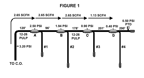
To show you how it works, let's assume you've been dispatched to leak locate on a single feed aerial cable that has three or four laterals (Figure 1). This is a classic example. If you haven't worked on this type of cable, you haven't worked pressure. And although we've used an aerial cable in this example, it could just as well be an underground or buried cable. The same procedure applies to all three.

The cause of the dispatch in this illustration is the 0.5 PSI pressure transducer reading at the end of the 12-26 pulp cable. By itself, this reading doesn't indicate much—not unless you know what the pressure is at the opposite end of the cable. A large pressure drop in this aerial cable would mean that you've got one or more leaks between the riser and the pressure transducer location. And that includes those five laterals.
So where are you going to work first? At the end of the cable, where the pressure is the lowest? If you've learned your leak locating techniques from the "old school" (see related story), you'd probably start at the end and work back to the air source. You can do this, but there's a better, more direct way.
By starting at the beginning of the cable (on the riser where the cable leaves the underground), you'll be able to take the pressure readings needed to calculate the air flow along the length of the cable. Once you know how much air the aerial cable is consuming, you'll know where to look and where not to look for the leak.
In this example, the pressure re corded on the riser is 3.20 PSI. Approximately 120 feet away at the first splice case location, a pressure reading of 2.50 PSI is taken. These readings provide the information for calculating a flow rate of 2.65 Standard Cubic Feet per Hour (SCFH). This flow rate makes it possible to immediately narrow the area of search by calculating a Zero Leak Projection (ZLP), and also determine whether or not you have passed the leak while inside the ZLP boundary.
To simplify the leak locating process, we recommend that you use System Studies' Leak Locating Worksheet E. This worksheet describes the procedures for leak locating in single feed cables. Worksheet E shows how ideal it is for calculating and recording the pressure and flow data in our example.
Using pressure readings, pneumatic resistance and the footage between readings, you can calculate a flow rate at each splice case location. If the majority of the original 2.65 SCFH flow is not indicated at a particular location, then you've passed the leak. It's that simple. When the flow falls off, turn around. The leak has to be somewhere between the last reading location and the one just calculated. This would include any laterals that branch off from the main aerial cable between the two reading locations.
Where Does It Change?
As you can see in Worksheet E, the flow calculated at each of the splice cases—with the exception of the last one—was 2.65 SCFH. This information indicates that the two laterals closest to the central office (Laterals 1 and 2) are not leaking. If they were, they'd be consuming a portion of the total calculated flow. There's no way you could have a leak in the first lateral and still calculate 2.65 SCFH at splice case B.
When a change in the calculated air flow occurs (such as splice case D), this indicates that a leak is present somewhere in the cable section between the last flow calculation point and the current one. Notice in the worksheet that the leak would have to be located either somewhere in Lateral 3 or in the section between splice cases C and D.
If there are any other pressure testing valves available, you can make additional flow calculations to further narrow down your search area. But before you do, make note of any changes in pneumatic resistance.
As you can see, this flow analysis technique can save you a lot of time and trouble when you have a number of laterals in your system. Eighty percent of the leak locating can be done from the main aerial cable. And when you do find the leaking section or lateral, you can usually pinpoint the leak's location by calculating another ZLP and a Back Projection.
If the cable section is single fed and there are no changes in pneumatic resistance, you can generally identify a leaking lateral or cable section in less than half the time it would normally take. The procedure is a bit more complicated if the cable section is dual fed and there are changes in pneumatic resistance. But it will still save you time.
So when things get ugly out there and you don't know which way to turn, use this procedure to get back on the right track.
© 1996-2018 System Studies Inc. All rights reserved.
(800) 247-8255 | (831) 475-5777