Overview
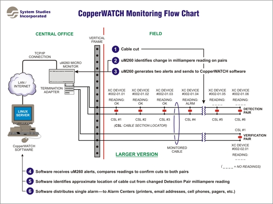
System Studies has developed a highly responsive monitoring system to help telcos apprehend the individuals who cut and steal lengths of copper cable. It is comprised of a server grade computer (running the Linux Operating System), CopperWATCH™ and PressureWEB™ software, one or more uM260 Micro Monitors™ (or 289H LSS™ monitors), and the use of two or more designated conductor pairs from each monitored cable. One of the pairs, called a Detection Pair, has multiple Cable Section Locators (CSLs) installed at designated points along the cable. The CSL devices are current loop (4–20mA) devices that have been encased in a protective cylinder and sealed to prevent moisture damage. Another dedicated pair in the same cable, called a Verification Pair, is equipped with a single CSL at or near the end of the monitored loop.
A maximum of seven (7) CSLs can be installed on one Detection Pair. The more closely spaced the CSL devices are installed, the shorter the identified theft area is for dispatched response personnel (police officers, private security personnel, etc.). Please note that additional Detection Pairs, each with seven possible CSL devices, can be used in long sections of cable for more precise cut cable detection. In this case, still only one Verification Pair would be required. If one or more cable sheaths branch off from the main cable, however, separate Detection and Verification Pairs will need to be designated for use in those lateral sections.
The software then determines the severity of the alert and compares the reading with the reading from the corresponding Detection or Verification Pair. If the actual cable has been cut, the Detection Pair provides location information, and the Verification Pair provides confirmation that both pairs have been cut (see image below). CopperWATCH then issues a single, immediate alarm and routes it to designated Alarm Center locations, telephone company individuals, security personnel, and/or law enforcement officials via email, cell phone text message, etc. A rapid response by these individuals can lead to the apprehension of thieves while they are still in the process or removing and/or transporting the stolen cable.
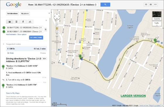
Notice also that there is a hyperlink at the bottom of the alarm that, when clicked, will display a Google map showing the section of cable in alarm (shown below). The targeted cable section will be highlighted on the map for a quick visual reference for response personnel.
Additional information regarding CopperWATCH software installation, data entry requirements and report access instructions are provided in the documentation that accompanies the software. Please contact System Studies for additional information, if necessary, or for answers to specific questions about the application.
System Studies has developed a highly responsive monitoring system to help telcos apprehend the individuals who cut and steal lengths of copper cable. It is comprised of a server grade computer (running the Linux Operating System), CopperWATCH™ and PressureWEB™ software, one or more uM260 Micro Monitors™ (or 289H LSS™ monitors), and the use of two or more designated conductor pairs from each monitored cable. One of the pairs, called a Detection Pair, has multiple Cable Section Locators (CSLs) installed at designated points along the cable. The CSL devices are current loop (4–20mA) devices that have been encased in a protective cylinder and sealed to prevent moisture damage. Another dedicated pair in the same cable, called a Verification Pair, is equipped with a single CSL at or near the end of the monitored loop.
Theft Detection
When read by the uM260, milliampere values from both the Detection and Verification Pairs will indicate if pair continuity exists, if there is trouble on either pair, or if a cable theft is in progress. The Detection Pair reading provides information about the approximate location of the cut (for example, if it is between two specified CSL locations or simply past a known location). The Verification Pair provides the confirmation that CableWATCH needs to generate an alarm dispatch on a cut cable.A maximum of seven (7) CSLs can be installed on one Detection Pair. The more closely spaced the CSL devices are installed, the shorter the identified theft area is for dispatched response personnel (police officers, private security personnel, etc.). Please note that additional Detection Pairs, each with seven possible CSL devices, can be used in long sections of cable for more precise cut cable detection. In this case, still only one Verification Pair would be required. If one or more cable sheaths branch off from the main cable, however, separate Detection and Verification Pairs will need to be designated for use in those lateral sections.
Software Response
What makes the uM260 Micro Monitor and CopperWATCH software so valuable in deterring cable theft are its rapid reading and reporting cycles. The uM260, for example, continually scans each Detection and Verification Pair approximately three times a minute—generating separate milliampere readings. If the uM260 detects a value on either of these pairs that deviates from the normal (OK) reading, it issues an alert and and sends it to the CopperWATCH software.The software then determines the severity of the alert and compares the reading with the reading from the corresponding Detection or Verification Pair. If the actual cable has been cut, the Detection Pair provides location information, and the Verification Pair provides confirmation that both pairs have been cut (see image below). CopperWATCH then issues a single, immediate alarm and routes it to designated Alarm Center locations, telephone company individuals, security personnel, and/or law enforcement officials via email, cell phone text message, etc. A rapid response by these individuals can lead to the apprehension of thieves while they are still in the process or removing and/or transporting the stolen cable.
Alarm Delivery
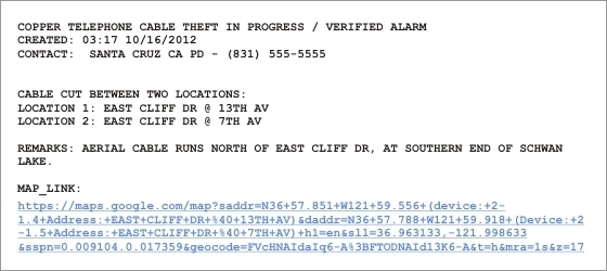
The screen below is an example of the email alarm format that CopperWATCH provides. Variations of this alarm are supplied for mobile devices designated as alarm centers. The "EAST CLIFF DR @ 13TH AV" text represents the Address information that was specified for device number 002-01.4 device during data entry. The second part of the location text, "EAST CLIFF DR @ 7TH AV," is the corresponding Address information for device 002-01.5, which is the next CSL installation location past the identified cable cut. The Remark "AERIAL CABLE RUNS NORTH OF EAST CLIFF DR, AT SOUTHERN END OF SCHWAN LAKE," is a detailed description of the cable section indicated by the alarm and is specified during data entry. The contact information "SANTA CRUZ CA PD - (831) 555-5555" is also specified during data entry and can be altered for each CSL device on a cable run to reflect cable sections that span multiple emergency responder jurisdictions.Notice also that there is a hyperlink at the bottom of the alarm that, when clicked, will display a Google map showing the section of cable in alarm (shown below). The targeted cable section will be highlighted on the map for a quick visual reference for response personnel.
Device History Information
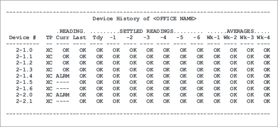
The screen below provides a sample of the type of information that would be displayed in the Device History option of the CopperWATCH software. This example corresponds to the device numbering shown in the first schematic above. It shows device readings for a Detection Pair (Device #s 2-1.0 through 2-1.6) and the corresponding Verification Pair (Device #s 2-2.0, 2-2.1). When a cut is detected, CopperWATCH sets the remaining CSL devices on the pair (past the cut) to no reading (----).Additional information regarding CopperWATCH software installation, data entry requirements and report access instructions are provided in the documentation that accompanies the software. Please contact System Studies for additional information, if necessary, or for answers to specific questions about the application.